World's First USB-C iPhone
For those who prefer a write-up
Introduction
Well I still can’t really believe it myself, but the project was succesful. I posted a short teaser video right after completing the project, and it blew up past a million views and I went from 100 to 20’000+ subscribers. Crazy. The press coverage was also pretty nice.
If you haven’t read Part 1 of this project, I suggest you do before we continue.
How did I finally make it work?
After my proof of concept, my next goal was to reverse-engineer the C94 board. The board didn’t look like it had many components, so I thought it wouldn’t be too complicated… Well actually the board has a first layer of glue on top of the components which is not too hard to remove, but then most of the components are covered by a composite material called underfill. It is used so that there will be less strain on the chips, but another consequence is that it is much harder for me or anyone else to remove them safely. While doing some research on the C94 connector, I stumbled across some articles mentioning that it had been hacked by someone in China and that fake connectors were hitting the market. I decided to do some research and went on Taobao, the Chinese eBay. It was a goldmine. I ordered all the board I could find. The thing is, they only ship to China. So what I did was to use an agent to ship my order to the agent’s warehouse in Mainland China. Then the agent shipped again that order from their warehouse to my place in Switzerland.
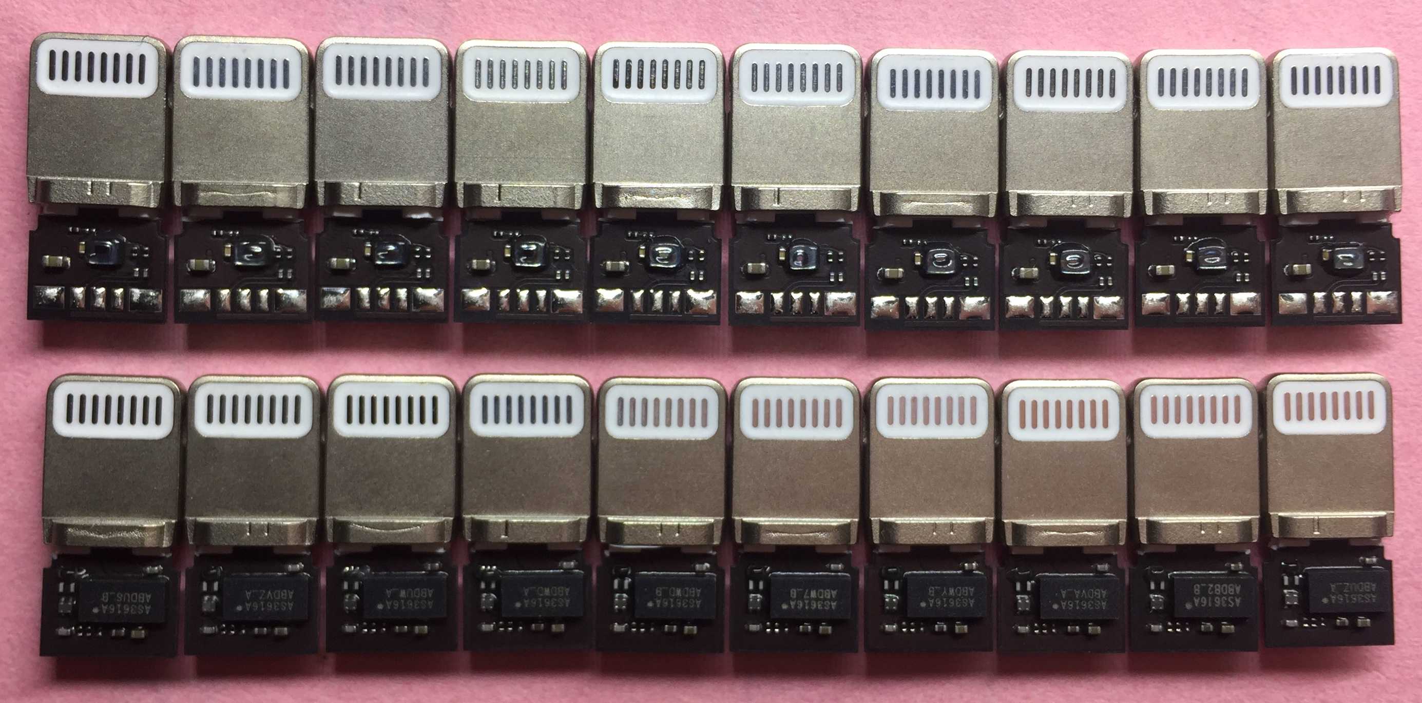
The boards arrived, and one of them caught my attention. It looked pretty damn close to the original, so that’s the one I chose. I thought, screw it, I will reverse-engineer the reverse-engineers. It will make my life much easier because there is no underfill, and also I’ll be able to share the schematics without infringing any Apple intellectual property. Perfect.
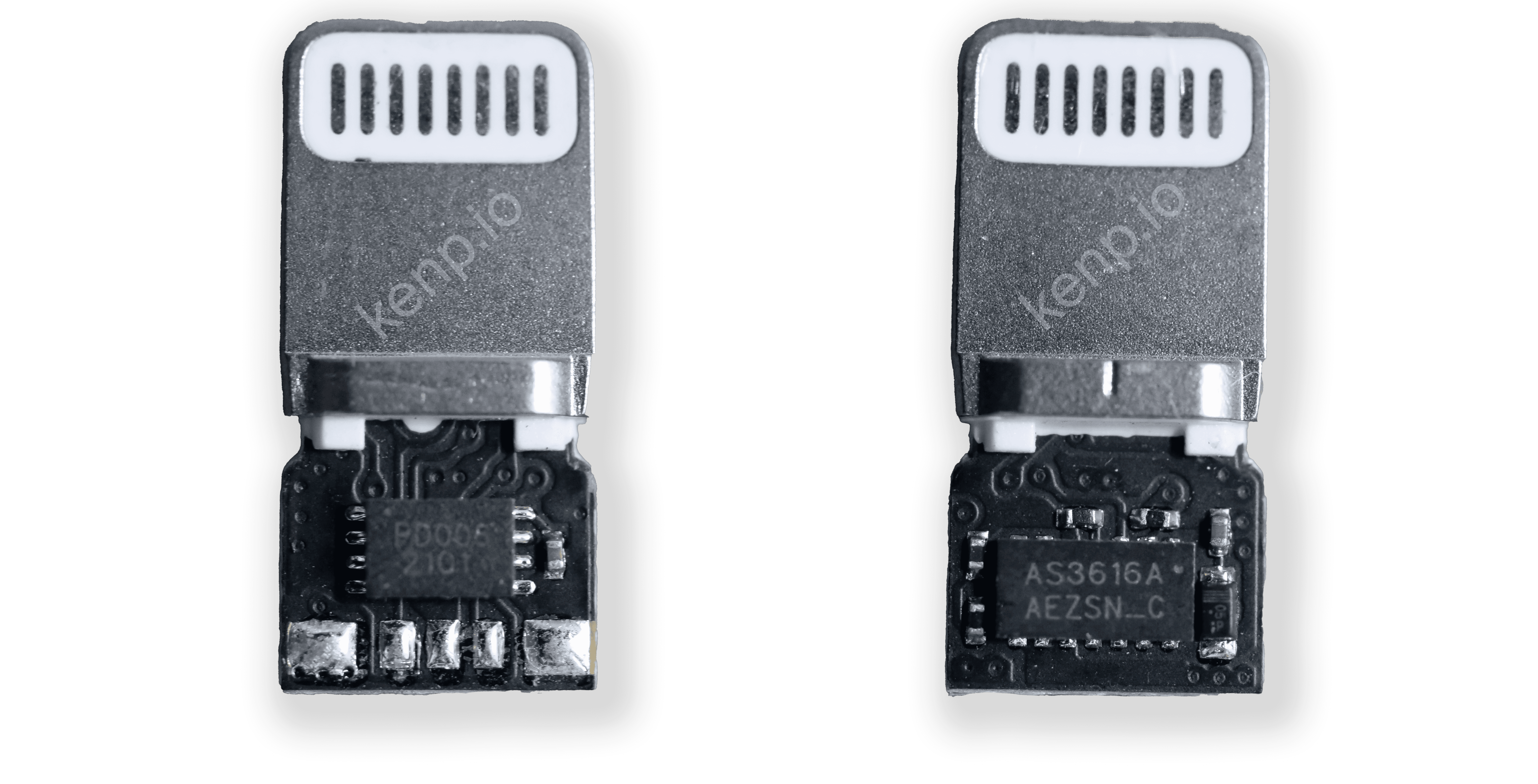
How do I recreate the schematics of this fakeC94 board? Well, the first thing I need to do is remove all the components on it. Then I run a continuity test between every pair possible of pads. Pretty straight-forward. Then I carefully measure the values of the components I can measure, and I document everything. And here we go, I now have everything I need to recreate the schematic.
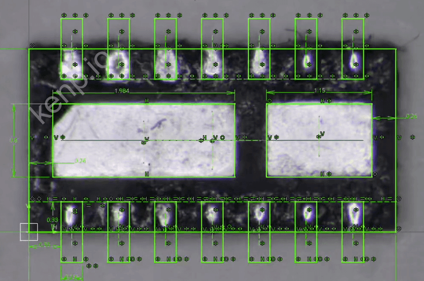
A schematic is good, but it is not enough to recreate completely the circuit and manufacture it. To make plans for my own PCB, I still need the footprint of every component. For most components it was easy as they are standardized components. But for the two main chips, where all the magic happens, I had to create my own footprints. To do this, I take a high-resolution picture of the chip and I precisely measure its outside dimensions. Then I bring the picture into a computer-aided design (CAD) software and I set the scale of my picture from my measurements. This allows me to measure smaller details such as the size and position of the pads. I do this for both chips, and now I finally have everything I need to order my own custom PCB.
I’m going to order a big rigid PCB first because it is much cheaper than a flexible one. This will allow me to check if the schematic is correct and works as intended. The PCB arrived in a few days. I prepared it by soldering to it the components I had stolen on the Fake C94 (F94) board. And it worked, sweet. Now we simplified our circuit even more, and we fully understand it. We can make it any shape we want. Let’s make it fit inside the iPhone!
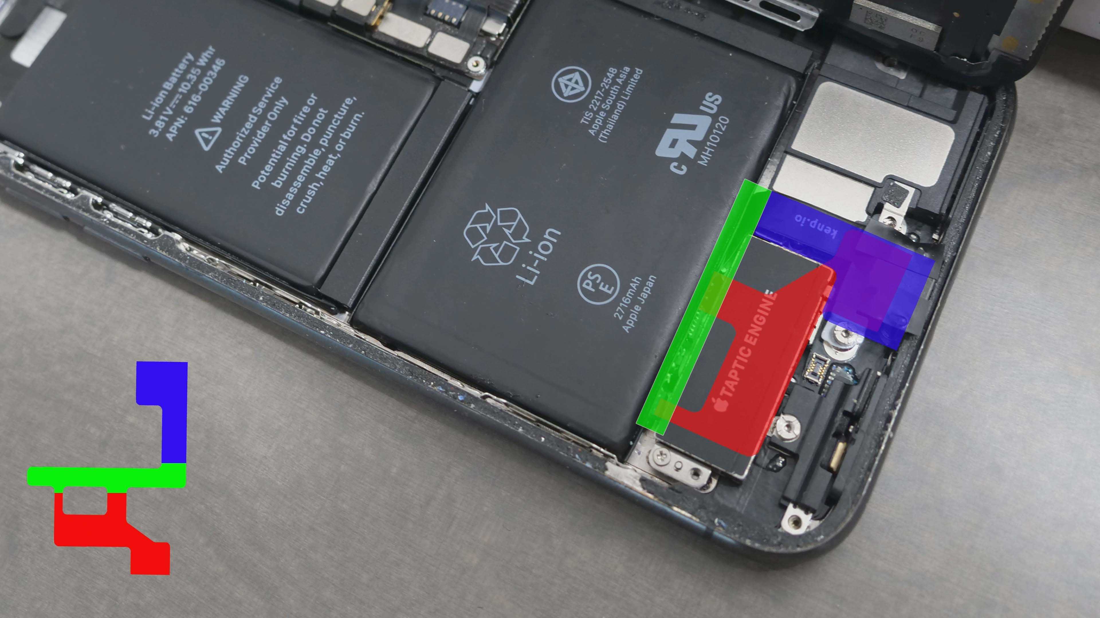
It didn’t take me long to spot something very interesting, there is a small gap in between the battery and the taptic engine, it runs through the whole width of the iPhone. And here is the trick that made it all possible. I thought, almost all the printed circuits in this iPhone are on the same horizontal plane. What if I make my circuit thin enough, and I place it vertically in the iPhone, in that small gap? There is only one way to find out, I need to try it.
First, remember that I’m still using wires to connect my board? This needs to go. I created a footprint with the same trick I used for the chips. Then, I needed to define what shape my board will have, and this needs to be very precise. I used a caliper to measure dimensions inside the iPhone, and also used a scan of the Lightning flex cable to help me out. Then I printed the final outline on a piece of paper to double-check that everything looked fine.
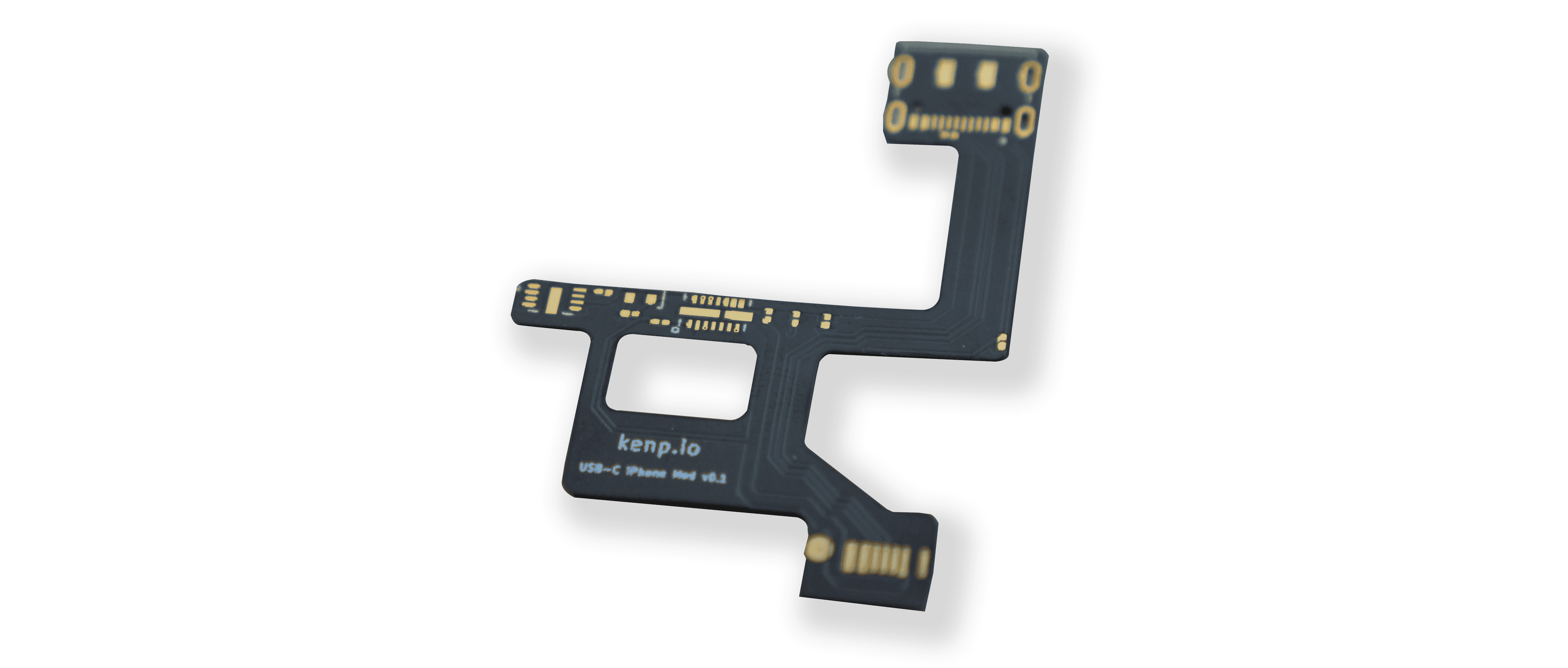
I can then import that outline into KiCad and place all the components. It becomes just a game to find a way to fit all the components onto that thin slice.
I ordered the board, and it arrived a few days later, what a beauty. I noticed I made some small mistakes, but they are not critical. Next, I transferred all the components from fakeC94 to that new PCB, and then soldered it to the lightning flexible connector.
The hole at the bottom of the iPhone is not big enough to fit a USB-C plug, I need to enlarge it. There are two ways to do this, the dirty or the professional way. I chose the latter. A CNC was programmed to increase the dimensions of the hole to perfectly match what we need. There were two main obstacles to overcome. The first one was that the iPhone has a back glass that would almost certainly shatter when I tighten it with the CNC vise. The solution was to design custom 3D-printed brackets that held the frame in place. The second difficulty was that you need to give an origin to the CNC for every axis so that it starts milling at the correct spot. This is not so trivial with an iPhone that has rounded edges everywhere. I used the method where you very slowly approach the drill and as soon as you hear a metallic sound, it means the drill touched the phone, and you can set your axis coordinate to 0. It was good enough.


There is one problem left, I need some mechanical support for the connector inside the iPhone. I figure the screen will push down on the connector, so it will be enough support in this direction, but I need support in the same direction as when I plug in a cable. To do this, I used 3d-printed part that was precisely designed so that is held by the two adjacent screw holes.
I assembled everything back. My custom connector goes under the taptic engine, bends 90 degrees and has vertical electronics. And then it bends 90 degrees again to bring the USB-C connector to the correct spot. I close the iPhone, the project is done.
This has been my biggest project so far. But judging from the support I received from you all, I am certain it is not the last. I am super motivated to tackle other similar projects.
So what’s next?
Well I’m happy to announce that the whole project is now open source on GitHub for those playing along at home. If you would like to port it to another iPhone model, have fun, and then please make a pull request so that everyone can benefit from it.
What will happen with this iPhone?
I decided to put it for auction! The funds will go towards buying advanced equipment. You can read more about this here.
That’s it for today, peace!